gpio-and-adc
GPIO and ADC
What is GPIO?
GPIO stands for Gerneral Purpose Input/Ouput. It usually refers to a set of pins on your computer’s mainboard or add-on boards. These pins are not designed for any specific purpose, and they can send or receive electrical signals.
What is ADC?
ADC stands for analog-to-digital converter. It is a system that converts an analog signal into a digital signal. It can be used to measure voltage and give the numberic result.
GPIO and ADC on Vivid Unit
GPIO
Vivid Unit comes with a 40-pin GPIO header, whose pinout is compatible with Raspberry Pi. There are two 5V power pins, two 3.3V power pins and 8 ground pins. The rest are I/O pins and they are all at 3.3V level.
The GPIOs are provided by RK3399, which has 5 banks (GPIO0 to GPIO4). Each bank has 4 groups (A, B, C and D) and each group has 8 pins (number 0~7). That makes 160 GPIOs in total, but only partial of them are routed to the 40-pin GPIO header.
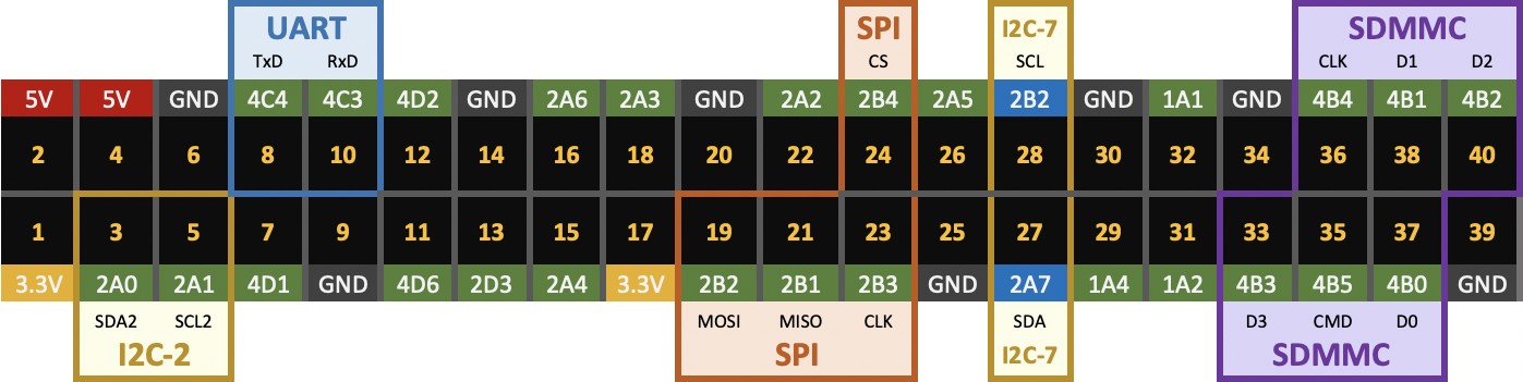
Remarks: in Vivid Unit OS, the SDMMC host is disabled in device tree by default, and hence GPIO4_B0~B5 are initialized as normal GPIO pins.
The GPIOs are named like these:
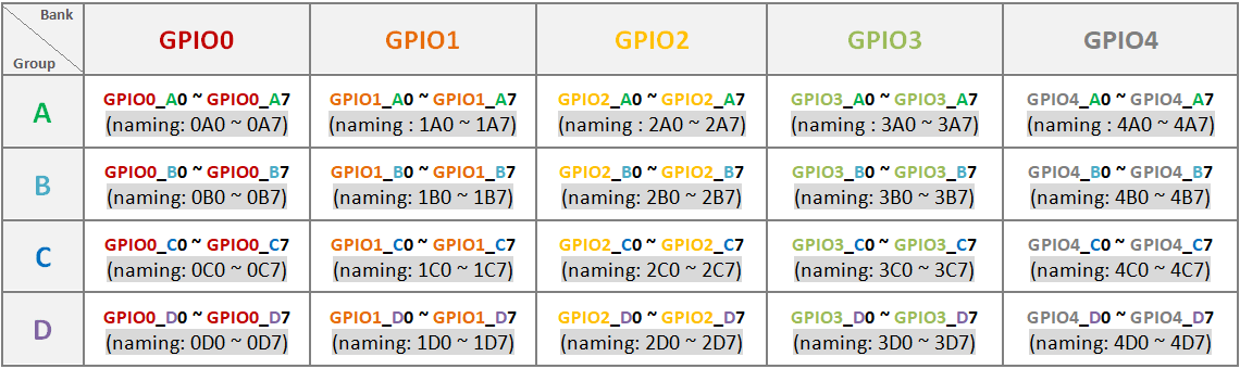
For the simplicity we use a short GPIO name for each GPIO pin. We put the bank number, the group name and the pin number in group together, to make the GPIO name.

For example, 2B5 is for GPIO2_B5, and 3C6 is for GPIO3_C6.
ADC
Vivid Unit also provides three 10-bit ADC channels (A0, A3 and A4). RK3399 provides ADC with 1.8V full-scale voltage, and Vivid Unit adds voltage divider and protection circuit (as shown below), to increase the full-scale voltage to 5V. The final resolution is 4.88mV.

It is safe to connect A0, A3 or A4 channel to any pin in the 40-pin GPIO header, because they can measure voltage up to 5V. If you want to measure voltage higher than 5V, you will need to implement an additional voltage divider.
This tutorial covers how to measure higher or negative voltage with Vivid Unit.
VGP Utility
VGP is an open-sourced application to control or monitor GPIOs and ADC channels on Vivid Unit. It contains two executables, one for command line interface (vgp) and the other for GUI enviroment (vgpw).
VGP is by default installed into the system. If it is not, you can always install it with:
sudo apt update
sudo apt install vgp
VGP in CLI (Command Line Interface)
Overview of 40-Pin
If you want to get an overview of the GPIOs in the 40-pin header, you can run:
vgp list
It will list the GPIO information in a format that similar to the wiringPi:

The value and voltage of all ADC channels are also printed at the bottom.
List All GPIOs
If you want to list all GPIOs, even including those pins that are not brought out to the 40-pin header. You can run:
vgp all
It will list the name, alternate function, value and mode for all GPIO pins:

Get Pin Mode
If you want to get the current mode of a specifi pin, you can use:
vgp mode [pin]
Here [pin] should be replaced with the GPIO name or physical pin number.
The result could be “IN” or “OUT”.
Set Pin Mode
If you want to set the mode of a specific pin, you can use:
vgp mode [pin] [mode]
Here [pin] should be replaced with the GPIO name or physical pin number, and [mode] should be one of these value:
- IN
- in
- INPUT
- input
- OUT
- out
- OUTPUT
- output
The “IN”, “in”, “INPUT” and “input” are the same, while the “OUT”, “out”, “OUTPUT” and “output” are the same.
Get Pin Alternative Function
The same physical pin can be configured to different alternative function. A pin can have up to 4 alternative functions (ALT0 ~ ALT3), and ALT0 is the default one. You can get the current alternative function for specific pin with:
vgp alt [pin]
Here [pin] should be replaced with the GPIO name or physical pin number.
The result can be 0, 1, 2 or 3, which means ALT0, ALT1, ALT2, ALT3 accordingly.
Set Pin Alternative Function
You can also set alternative function for specific pin with:
vgp alt [pin] [alt]
Here [pin] should be replaced with the GPIO name or physical pin number, and [alt] should be replaced with the alternative function (0, 1, 2 or 3).
Get Pin Value
To get value for given pin, you can use:
vgp get [pin]
Here [pin] should be replaced with the GPIO name or physical pin number.
The result could be 1 (high) or 0 (low).
Set Pin Value
To set value for given pin, you may use:
vgp set [pin] [value]
Here [pin] should be replaced with the GPIO name or physical pin number, and [value] should be 1 or 0.
Wait for Interrupt
If you wish to monitor the state of given pin, you may use:
vpg wfi [pin] [edge]
Here [pin] should be replaced with the GPIO name or physical pin number, and [edge] should be rising, falling or both.
This command will block until the state of the pin changes.
ADC
You can read the ADC result at specific chanel with:
vpg adc [channel]
Here [channel] should be 0 (for A0), 3 (for A3) or 4 (for A4). The result is a number (0~1023). If you want to get voltage value, you may use:
vpg adc [channel] v
By adding a lower case letter v as the last argument, this command prints out the voltage value (for example 4.21). If you want to print out the voltage value with the unit (V) together, you may use:
vgp adc [channel] V
By adding an upper case letter V as the last argument, this command prints out the voltage value with unit (for example 4.21V).
Get Help Information
If you need help during usage, you can run this command to get help information:
vgp --help
VGP in GUI (Graphical User Interface)
You may run the GUI version of VGP via the "System" category in Applications Menu.

You may also run “vgpw” in command line terminal to launch the same GUI application.
You will see the interface that represents the 40-pin header:
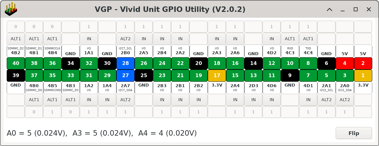
The value of three ADC channels are also listed at the bottom, including the raw values (0~1023) and the voltage values. These values refresh for every second.
There is a “Flip” button at the bottom right corner, and you can click it to flip the view.
You can click the mode button for each pin to change its mode or alternative function. The possilbe mode/funtion could be IN, OUT, ALT1, ALT2 or ALT3.
When the mode is set to OUT, you may click the value button to toggle the pin’s value.
When the mode is set to IN, its value will get updated automatically when the pin is pulled up or down.